
PROJECT
T7 Hard Drive Case Build
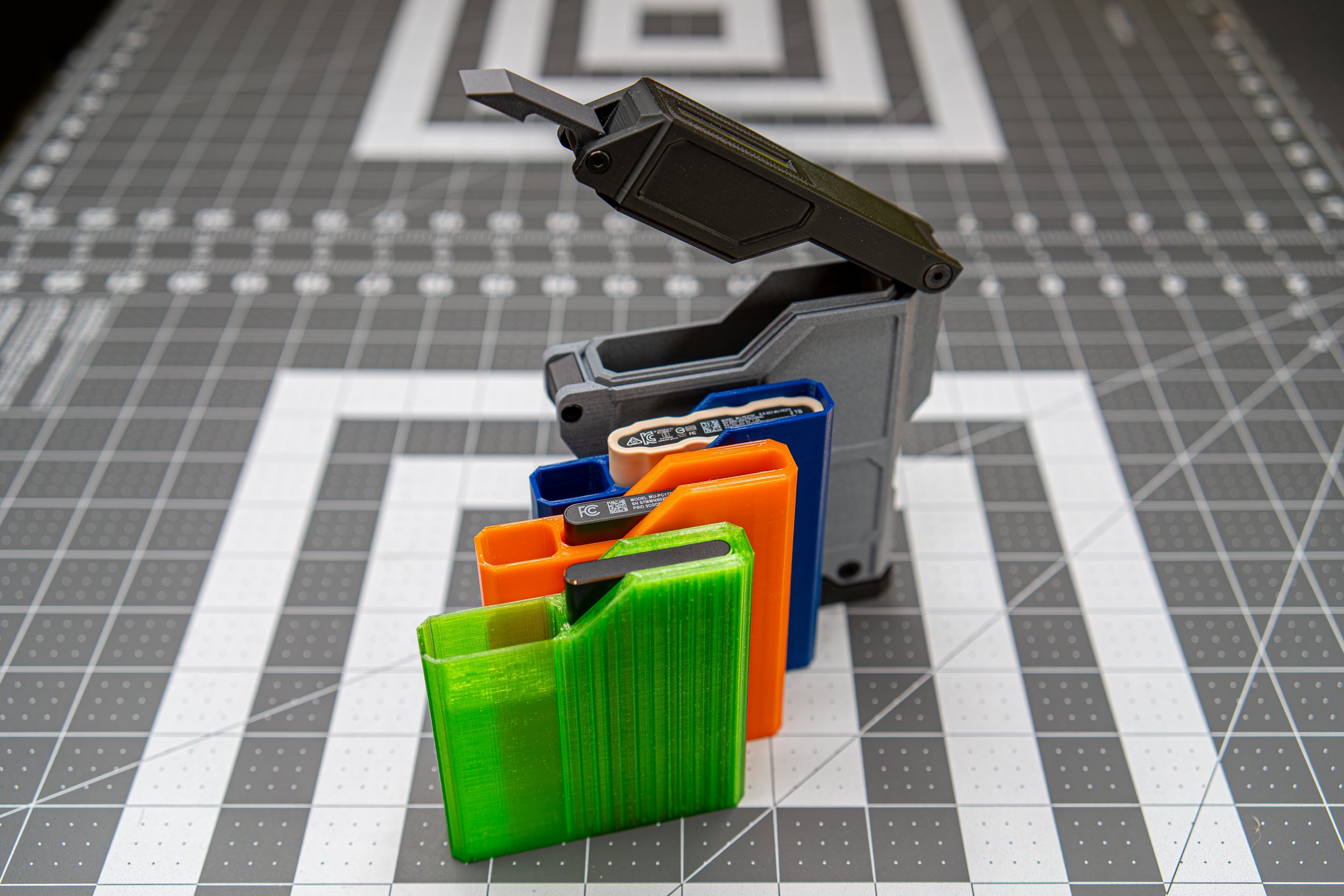
There was a lot of interest expressed for the T7 hard drive case featured in one of our shorts. So we went back and further refined the file to improve function and durability.
The following serves not only as a record of the steps we took in the process, but also as a document of what we learned along the way.
If you want to try printing and building one of these yourself, we’ve made the files available in our store.
Reference files can be found in the Materials Reference accordion at the bottom of the page
Some improvements we made
Dust Sealing
We added additional dust sealing to the top and bottom of the case design. Modifications were made to the structure and shapes of the parts, as well as accommodation for a flexible rubber cord to be used as compression seals.
A Better Lid Hinge
A design flaw of the main hinge was also addressed. The new design uses a two-part configuration that orients the layer lines for each part in directions optimal for strength.
Having the hinge inserted as a separate part also leaves open the possibility of designing different lids; maybe one that offers more vertical clearance, or perhaps one that has a slot for a label, or if you want to change the pivot point for some reason.
Magnetic Latch
A new magnetic latch replaces the older snap latch. In addition to improving visual and tactile refinement, the magnetic latch should last longer than the snap latch because it does not subject the plastic to the repeated strain of stretching over the metal screw.
Insert Sleeves
The most recent set of design revisions replaces the previously, built-in cavity divider with an insert sleeve that serves the same function. This allows the sleeve to be removed and replaced with other sleeves with different configurations. And because the sleeves are printed in flexible material, they also provide additional shock protection for the case contents.
How we built the case
Printing the Shell
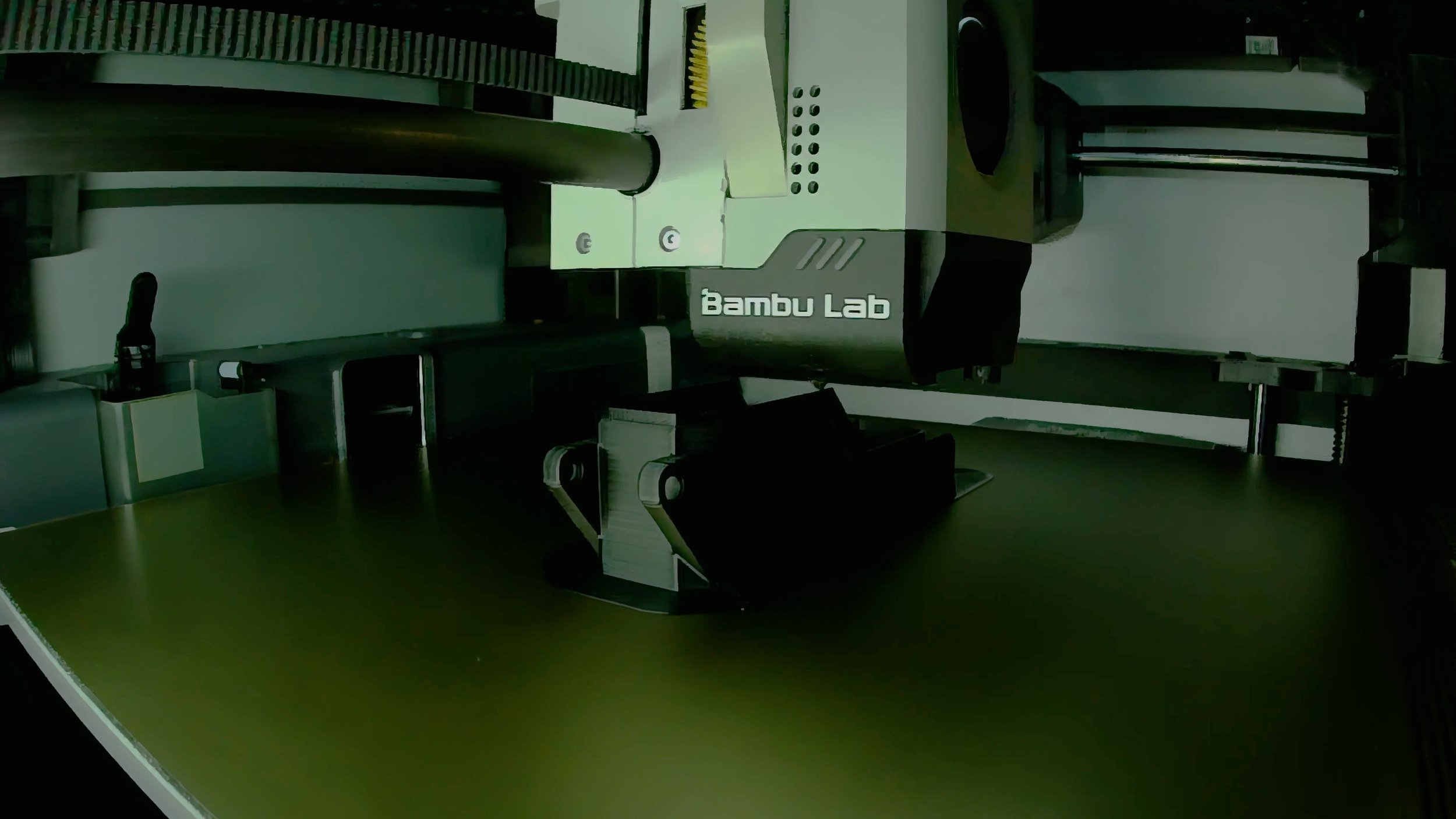
The Main Shell was printed vertically, in part because that resulted in the strongest walls, but also because it resulted in the cleanest outer surfaces. The bottom surface is not continuous on the plane, so supports will be required at the two raised portions. A brim will also help to keep it in place to counteract any potential warping. Setting the brim farther away than average, maybe at 0.2 mm, will help to make sure it detaches smoothly. With all above, printing the shell will use approximately 105 g of filament.
Printing the Rest
For similar reasons, the lid was also printed vertically, but upside-down to avoid the necessity to use supports. The base was also printed vertically, though we paused printing twice to add two different sizes of magnets. The hinge insert and latch, however, were printed on their sides. Note that the hinge insert will require supports. The lid, base, latch, and hinge collectively took about 60 g of filament.
Two Stage Magnet Insertion for the Base Component
Since we wanted there to be enough magnetic strength for the loaded case to hold itself up, and we could not find a suitable single magnet to fit the design, we ended up working with three relatively strong magnets. The magnets were inserted in two different stages to minimize interference between them during the embedding process. The design of the 3D model was adjusted to accommodate this strategy, with their cavities slightly staggered in height within the model. First the two round magnets farthest away from each other were dropped into place. The Bambu X1C uses metal build plates, so this helps keep them in place, but if your printer does not use metal build plates, you can use a drop of glue in the cavity prior to placing the magnets.
Completing the Embedding Process
Then the print was unpaused until a few layers sealed the first two magnets securely into place. The print is paused a second time to insert the larger rectangular magnet. Doing it in this way prevents previously placed magnets from being pulled out of their cavities by the magnet you are currently trying to put into place. Once the last magnet is inserted, the print can be unpaused till completion.
From Drawings to Templates
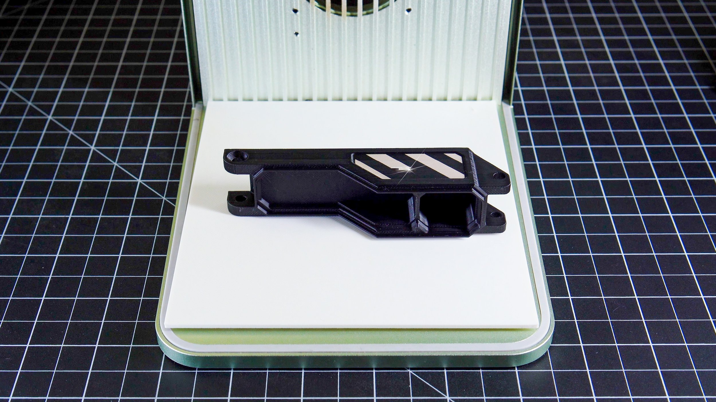
In Shapr, we output a plan view of the case (using the ‘File > New Drawing’ function) at actual size (1:1) in PDF format. Then importing that into a vector-editing program such as Adobe Illustrator or Affinity Designer, the vector elements from PDF can then be used as a guide to create graphics that accurately fit the panels and facets of the piece. Keep in mind that the laser can either render shapes as solid fills with the engrave function, or as lines with the score function.
Importing graphics into xTool Creative Space
When design of the graphics is complete, they should be saved in SVG format. You can either import outlined text from the vector program, or choose to add the text in Creative Space, where you will have the option to edit it as text. With more complex designs, the layer function in Creative Space can help to group your element into more manageable categories.
*Links to the sources of the typefaces used in the sample graphics for this project have been included in the ‘Sources’ section of the accordion menu at the bottom.
Run Test Plates of Filaments You Plan to Use
To get the best possible results when using the laser on your prints, it's always a good idea to run a test plate to find out the range of effect you can achieve and the optimal settings to get the sharpest, highest contrast lines. In fact, you may want to do a test like this before you commit to printing a part using a specific filament.
Outline Engraved Shapes for Crisper Edges
For our test graphics here, each of the major sections rendered with the engraving function were also outlined with the score function. This gives the edges a much crisper look.
Cleanup and Heat-set Insert Fitting
Since many of the fastener holes needed to be printed perpendicular to the build plate, they required a bit of cleanup prior to assembly.
The cleanup also made it easier to pre-fit the heat-set inserts to ensure they were level before applying the heat and pressure with the press. For the lid, it was an M3 insert.
Upper Gasket Installation
The groove in the upper seal has been modeled to fit 1mm rubber cord that acts as a compression gasket. It takes a bit of care and patience to get in there, but once it’s in there, it should stay put. We started on one end, then gradually worked our way around.
A small flat plastic tool can help to push the cord into the groove. Avoid using any sharp metal tools such as a screwdriver to avoid marring or nicking the cord.
You can probably print a 1-1.5 mm stick, then just round the edges of one end with a nail file or emery board.
Upper Gasket Trim
Once you’ve gotten all the way around back to the other end, the trick is to cut the cord so that there is no gap between the ends.
Start with a bit of overlap, then trim small amounts and repeatedly check fit until you’re happy with the result.
Remember to continue to make sure that the rest of the cord is properly seated in the rest of the groove before trimming any additional cord.
Heat-set Insert Into the Main Shell
Just like the lid, the main shell also uses an M3 heat-set insert.
Assuming that you’ve made the hole for the insert just big enough, using something flat can help snap the insert into place and at the right angle for the press to come into proper contact. Remember not to push down too far with the press. This can’t be undone.
Heat-set Inserts Into the Base
Four M4 heat-set inserts are Used for the base. You’ll likely need to change the tip on the heat-set press. For safety reasons, it’s always better to turn the press of, and let it cool before unscrewing the M3 tip to swap it out. This is one area where it was important to make sure the inserts were pressed all the way in so that the top edge was flush with the outer surface of the base. If the plastic bubbles up around the edges of the insert, it can be filed or sanded down once it cools completely. It needs to fit snugly but easily into the shell.
Heat-set Insert and aluminum spacers in the hinge
None of its sides are completely flat, so I used the yellow plastic stick to make sure it sat level as I pressed the heat-set insert for the retainer screw in. Those inserts stay hot for a little while, so be careful not to burn your fingers or lay them down on anything that can melt or get damaged. We’ve updated the design to use aluminum inserts in the hinge pivot.
Pressing in aluminum inserts
Using the PLA Pro or the PLA-CF, the hinge cavities for the aluminum spacers print pretty accurately; so the spacers fit snugly and securely, but are still able to be pushed in primarily by hand.
Flush fit
Properly installed, the spacer faces should sit flush with that facet of the hinge. This should allow the nylon washers to fit on either side of the hinge head with very little play.
Sleeve Print and Cleanup
We tried printing the insert sleeves in both TPU 95A and 95A HF (or High Speed). Both worked well, so if you can find a color you like in the high-speed variety, it could save you a lot of print time. We also tried TPU AMS, but it was significantly harder/stiffer (at a reported 68D durometer).
We used Castroviejo scissors to trim any minor stringing we found inside the cavity, then used a long neck lighter burn off anything we missed.
Inserting the sleeve
We designed/sized the sleeve to print so that they insert fairly easily into the main body, but sit snugly inside. The layer lines of the sleeve and the main body meshing against each other may make pulling the sleeve back out a bit difficult, but we found that wiggling the sleeve side-to-side while pulling seemed to help.
Lower Gasket
For the lower gasket, 2 mm hollow rubber cord was used. Because it’s hollow a small piece of the 1 mm cord can be used to connect the two ends together. Once installed, the cord acts as a crush gasket.
The installation process is similar to the upper seal, but this one seemed a bit easier, because the cord was much thicker and remains raised above the top surface of the base.
Cutting Foam with the Laser
Again, using the vector drawing output function in Shapr3D, we imported the shapes of the inside of the lid into xTool Creative Space and cut foam pads to fit that interior surface.
Attach Foam
Using 3M heavy duty mounting tape the 2mm thick foam pad was attached to the inside of the lid. With the design revision incorporating the insert sleeves, the foam previously attached to the base was no longer needed, but the files for cutting them are still included in the file set in case anyone wants to use the previous construction method.
Bolting Everything Together
The base should slide pretty easily into the shell, and it takes just a bit of pressure to compress the gasket to get the holes to align. If it doesn’t, check that heat-set inserts have been pressed-in properly.
Similarly, the hinge insert should slide in smoothly but snugly with little to no play.
Inserting the Nylon Washers
The plastic washers may be a tight fit, but once they’re in there, they really help to eliminate torsional play in the hinges while still preventing the hinge from binding, even if slightly overtightened.
The M3 washers were probably one of the most frustrating things to install. The easiest way might be to put the case on its side with the chamfered hole facing up, balance the first washer on the latch’s side already aligned, carefully position it in place without knocking it off, then sliding the screw through once you're sure all three things are aligned.
Then you can try to get the second washer in between the latch and the main shell before pushing the screw all the way through.
Tightening the Screws
Countersunk screws should seat flush, flat, and tight, but avoid overtightening, especially since most of them are not oriented optimally in relation to the layers.
For some reason, 23 mm M3 countersunk flat head hex sockets were somewhat difficult to find. If you have the same experience, you can always get them in the 25 mm length and cut or grind them down to length so that they don’t protrude past the edge of the M3 heat-set inserts.
Completed Unit
Once completed, the case should provide a precise fit for a Samsung T7 Shield SSD portable drive. The cable cavity seems to work best with shorter (6 inches) USB-C cables with fairly narrow plug housings.
Magnetic Base
The optional magnetic base allows the case to be attached to magnetic surfaces. Please note that using the magnetic base is not advised when storing magnetically sensitive items in the case, including mechanical drives or cards with magnetic strips.
Your Own T7 Case
If this has gotten you inspired, and you want to try building one yourself, the files are available in our store. We’ve also got some hardware kits available to take some of the guesswork out of the assembly process. And for those who don’t want to go through the trouble, we’re making some completed units available. While the files should be available indefinitely, we’re only doing a limited run of the physical items — a small batch ;)
-
If you are interested in what we used for this process, you can find our materials below.
Hardware:
Bambu X1 Carbon
WhamBam 258 x 258 Flexi Plate with Pre-Installed PEX Build Surface
xTool F1
Heat-set insert press with tips for M3 and M4 inserts
Software:
Shapr3D Version 5.710.0 (7459)
Bambu Studio 1.9.7.52xTool Creative Space v2.2.21
Materials:
2x M3 countersunk flat head screws 22 mm (hex socket preferred)
4x M4 countersunk flat head screws 8 mm (hex socket preferred)
1x M4 countersunk flat head screw 6 mm (hex socket preferred)
2x M4 countersunk flat head screws 10 mm (hex socket preferred)
2x M3 heat-set insert 4mm deep
7x M4 heat-set insert 4mm deep
2x M4 Nylon Flat Washers 10 mm OD, 4 mm ID, 1 mm Thickness
2x M3 Nylon Flat Washers 6 mm OD, 3 mm ID, 0.5 mm Thickness
2x M4 Aluminum Spacers 4.1mm ID x 7mm OD x 4mm L (5mm L could be a ‘perfect’ fit, depending on print settings, but 4mm is safer )1 mm solid rubber cord (30 cm length)
2 mm hollow rubber cord with 1 mm internal hole/channel (30 cm length)
6 mm thick EVA foam sheet
2 mm thick EVA foam sheet
0.4 in width heavy duty mounting tape
1x 60 x 10 x 5 mm rectangular magnet2x 10 x 5 mm round disc magnets
-
-
Typefaces
Modernista (single line font)
Anero
Barkmo
Aoi Mono
*Please remember that using lasers on synthetic materials always runs the risk of putting harmful chemicals into the air. So, before beginning, don't forget to ensure that you have proper ventilation and to use hoods and air filtration whenever possible.


