
EXPERIMENT
Laser engraving 3D prints
Part 2: Troubleshooting
It can be challenging to get the results one expects when attempting to use a laser to render a design onto a 3D printed piece. We go over a few ways to help troubleshoot some of these potential issues and gain a better understanding of the material you’re working with.
Reference files can be found in the Materials Reference accordion at the bottom of the page
Establishing a material profile
When using the laser to apply graphics on prints made with certain filaments, we noticed that we were sometimes getting inconsistent and uneven results when using the ‘engrave’ setting. Parts of the design were printing darker and a little blotchy.
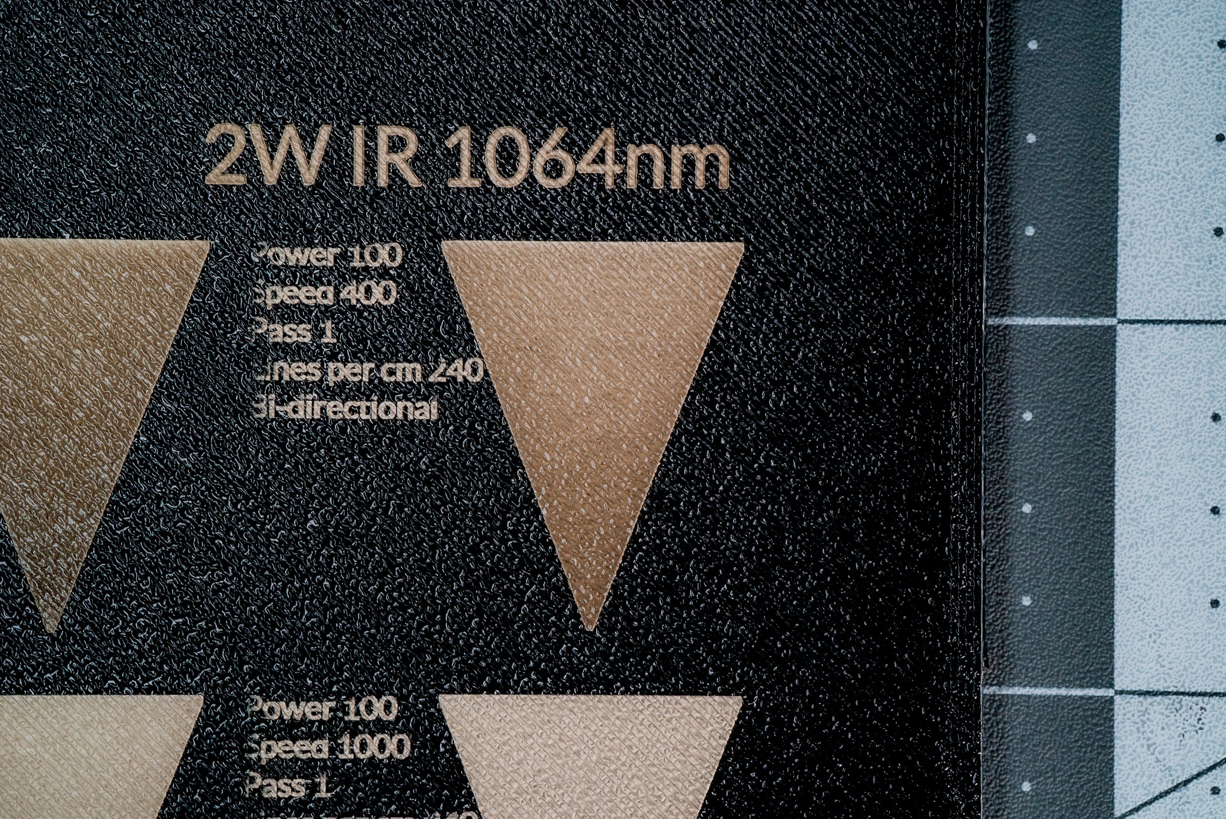
First we needed to confirm our theory that variable widths in the design had a bearing on the effect. A simple triangle that gradually tapered from wider to narrower would give us the answer. We set up three. The first with the same settings we had been using on our most recent project. The second with a faster speed. And the third with the raster set to uni-directional instead of bi-directional.
The second test was to find out if the configuration of the SVG vector file made a difference.
One was set up with many objects arranged as a unified, compound shape; which the engraving software would rasterize as if it were a single shape, with each pass of the laser spanning the entire width of the design as it passed from top to bottom. The other was set up with each element as a separate shape; prompting the software to render each element accordingly.
The third test was a series where we modulated speed, lines per centimeter, and power in separate sequences.
First off: ‘yes’, raster width has an effect on the issue. Apparent in both the triangle tests, as well as the compound versus separate shapes SVG configurations. In fact, the narrowest part of the initial control triangle was essentially burned and melted.
Too much power and/or for too long of a duration in the same area on the surface of the piece.
This is reinforced by our findings in the second test: the final, bottom square of the compound SVG was the darkest and also showed signs of melting. And it makes sense that all separate shapes in the other SVG configuration look the same as the bottom square in the compound shape.
The third test essentially establishes the stable working parameters for the IR laser on this filament: Either the power should be set at 100 and the speed set at 1000; or the power is set at 50 and he speed at 200. There are probably other equivalent modulation ratios in between, but these two are confirmed.
We also did a second set of tests on an additional plate. These tests modulated speed while keeping power constant at 100. The intent was to see if there was a speed setting that allowed the quality of the applied graphics to be unaffected by changes in rasterization width. These tests confirm that at power 100 and speed 1000, graphic application remained consistent for this filament.
Also, remember that different filaments respond in very different ways to the same settings. For example, this dark brown PLA has a much different ‘sweet spot’ than the black PLA we’ve used for most of this test. The brown looking like it’s responding better to slower speeds and slightly higher power, but never achieving the crisp contrast that the black does.
Filament-Laser-Test-B
Filament-Laser-Test-C
These test files are specific to the xTool F1, so they likely won’t be compatible with other types of machines, but you may find them useful for reference or as a starting point.
You can download them from the Materials Reference section at the bottom of this page.
Managing rasterization
If you’re still having issues with overburn banding on the narrower parts of your design, there is one more thing you can try. As mentioned before, when the laser moves from a wider portion of the design to a narrower one, it has a higher chance of more quickly heating up that smaller area.
On a side note; this principle is also precisely why merely scaling a design up, or down can drastically change the way the laser renders the same file on the same material. All things being equal (including speed and power), the difference in the distance that the laser travels causes enough change in sustained temperature that the resulting difference in imprint characteristics and appearance can be quite significant. So testing at the same size on the same material is ideal.
But back to retaining imprint consistency within the same design: If you add a thin bar on either side of your design that are equal in height to your design, it will effectively force the galvo mirror to rotate the same amount, making those raster lines equal in width as it progresses down the design. But you’ll have to remember to place those lines far enough from your design so that they fall onto the bed and are not etched into your piece as well.
Keeping the instrument clean
We were also getting another type of blotchy inconsistency; that appeared to have less of a correlation to specific raster lines than the previous issue. With this, it seemed like the laser was actually failing to make contact with the material.
Remember that just like cameras, lasers operate using light passing through lenses. And in the same way oil or dust on camera lenses degrade the quality of the image, debris or haze build-up on laser lenses can affect their performance. We had been getting some other ‘gaps’ in the graphics, but after carefully cleaning the field lens, the problem went away.
Conclusion
Because there seem to be so many variables, and the way different filament materials react to contact with the laser can be so unpredictable and inconsistent from one material to the next, it can feel pretty daunting and discouraging to embark on this endeavor. But as with anything worthwhile, experimentation leads to experience, and experience leads to understanding. And with this especially, gaining a better grasp on the processes limitations has begun to shift the way we think about working with it; to add a step at the beginning of a project to test how a material will respond to laser contact prior to making any assumptions. In some ways, it’s a bit more like working with wood or ceramic glaze.
Before
After
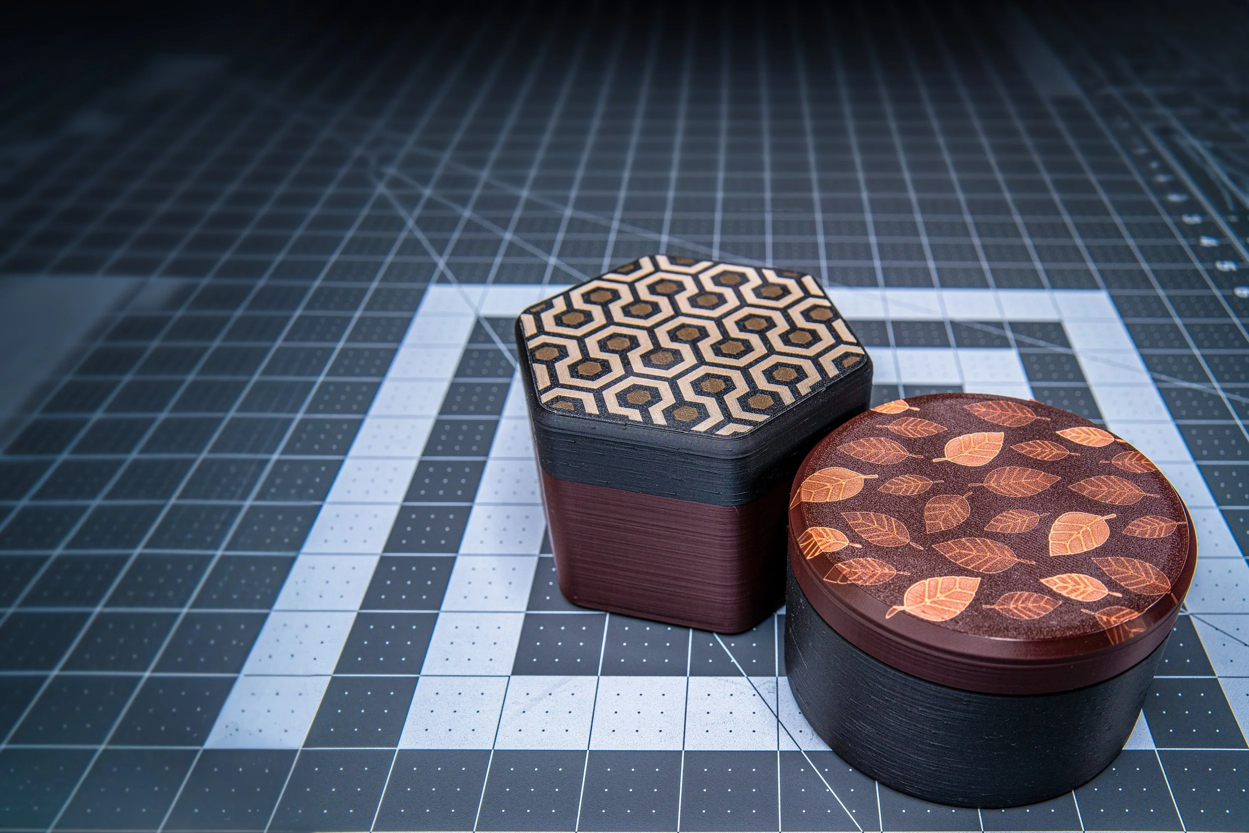
But combining what we learned here, with what we learned in the previous exercise, we've been able to both improve the quality and the sophistication of what we can achieve. While this video focused primarily on working through some challenges related to the 'engrave' function in the laser software, you can see from this example piece that combining that with some elements using the 'score' function can yield some pretty impressive results.
Please remember that using lasers on synthetic materials always runs the risk of putting harmful chemicals into the air. So, before beginning, don't forget to ensure that you have proper ventilation and to use hoods and air filtration whenever possible.
-
If you are interested in what we used for this process, you can find our materials below.
Hardware:
Bambu X1 Carbon
Bambu Textured Plate
xTool F1
Software:
Shapr3D Version 5.541.0.6373
Bambu Studio 1.8.4.51
xTool Creative Space
Materials:
Black PLA
Brown PLA
Fabrication Files:
Filament Laser Test A (xcs - 754 KB)
Filament Laser Test B (xcs - 1 MB)
Filament Laser Test C (xcs - 1 MB)
Leaf pattern (xcs - 117 KB)
Hexagon pattern (xcs - 164 KB)
Hex Box (3mf - 538 KB)
Round Box (3mf - 374 KB)


