Using Shaper Trace to support 3D modeling / printing
A Shaper Trace can be a great addition to a workflow, speeding up the translation of flat or drawn assets into more machine-friendly vector/SVG format. In some cases, circumventing the need for traditional measurement and drafting steps.
A sample scenario to illustrate the potential
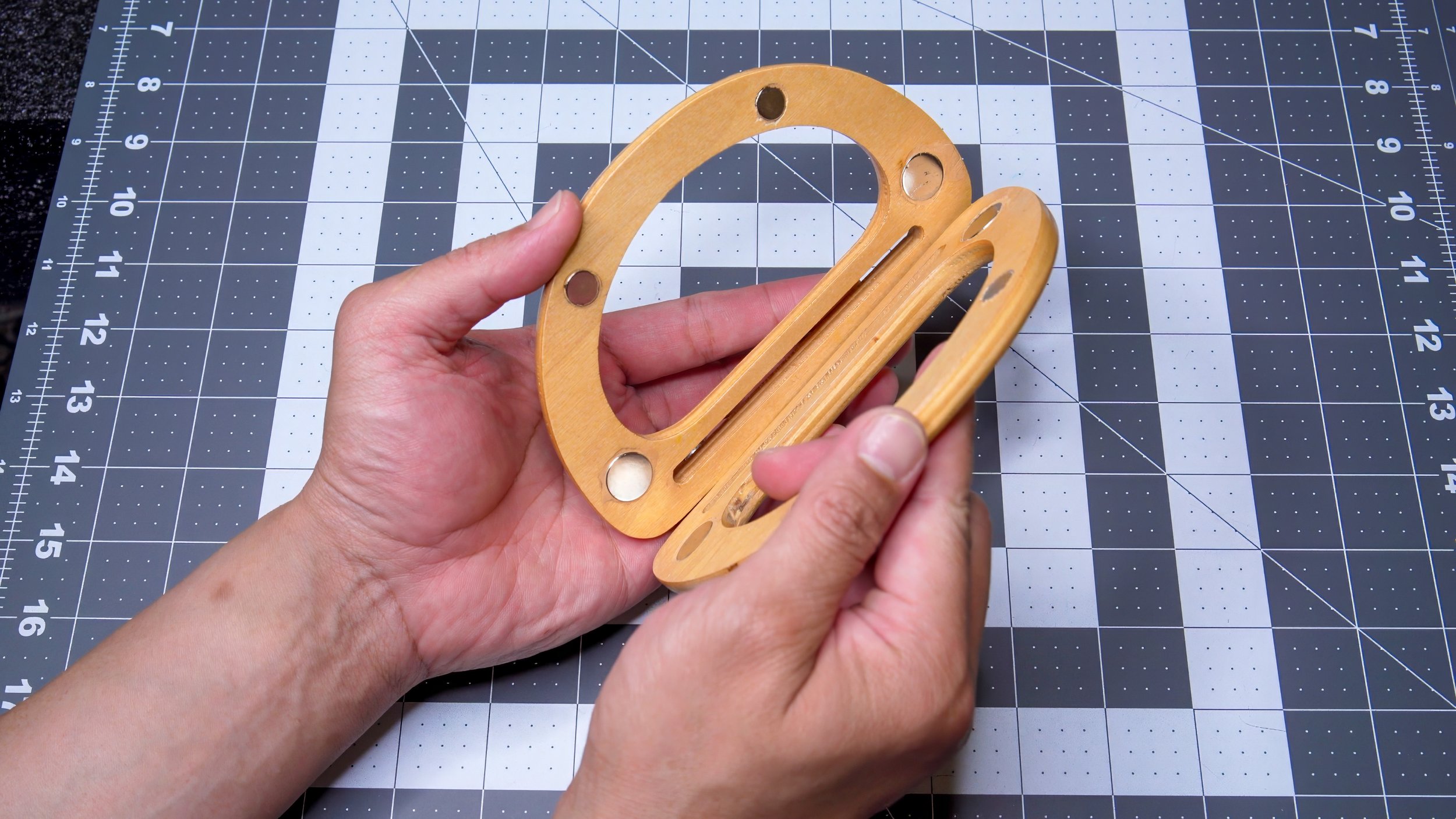
Here, we take the common (or at least easily understood) process of marking a wooden piece for routing shallow cavities to insert some round disc magnets. The conventional approach would be to measure and mark each part, being very careful to make sure paired parts matched up properly. This method is rife with potential points for human error. The following is one method that could not only speed up the marking of multiple parts, but also improve consistency.
Creating a tracing template with Shaper Trace
The first step is to use the Shaper Trace to obtain line information that will useful for your goals.
The Shaper Trace is instantly able to convert any flat linear graphic into SVG vector format. Once in vector format, it can be edited with vector editing software such as Adobe Illustrator or BoxySVG.
Normally, you would place the side/surface of the part you want to work on a piece of clean paper. Then trace it with a pen or pencil. But because the part we were working with here was pretty flat as it was, we were able to scan the part itself.
Using the Shaper Trace app and the camera on a mobile device, the Shaper Trace takes an image of the frame, and whatever is inside it, then converts it that image into an dimension-accurate SVG vector representation.
That SVG file can then be imported into a vector editing program — in our case; Adobe Illustrator. This is where we added additional markings that corresponded to the magnets we planned on inserting into our wooden handles.
When vector edits are complete, the file saved, then output as a DWG file (Illustrator will output as DWG, but if using another vector editing program, online conversion resources can be used)
The DWG file can then be imported into CAD software such as Shapr3D. Once there, this flat vector file cane be used to create solids that match in dimension to the parts they were derived from in the real world.
In this case, the vector file was used to create a 3D model that, once printed, could be placed snugly on top of the wooden part the vector part was derived from.
We used a Bambu X1C to print the 3D model we designed in Shapr3D.
Once the printing was complete, we test-fit it over one of the wooden handles.
We used a Sharpie and our new template to make the marks that will be used as guides to route the cavities for magnets.
With the template we were able to do with much more quickly than measuring and marking for each circle on each part individually.
Using these marks, we could then bore out the cavities for our magnets.
We then glued the magnets into these cavities.
The magnets installed.
This project was done primarily to test the idea and concept. But as we worked through it, we realized that instead of using this method to create a mere marking template, it could just as well be used to create more substantial routing guides that can be used on a proper routing setup. The tool would just need to be made thicker to avoid any flexing.


